About turning and milling
The turning and milling composite equipment not only improves the efficiency of the process, but because the parts are only loaded once in the whole process, the precision of the processing is more easily guaranteed, and the production process chain is greatly shortened. Moreover, it is only necessary to hand over the processing task to a job, which not only simplifies the production management and planning, but also significantly improves the transparency, and can quickly solve and optimize what is happening without a complicated planning system. The more complex the workpiece, the more obvious its advantages over the traditional process-dispersed production methods. In addition, despite the high price of a single machine for a complete machine tool, due to the shortening of the process chain and the reduction in the number of equipment, the floor space and equipment maintenance costs are also reduced, thereby reducing the investment and production operations of the total fixed assets. And the cost of management.
The development of turning and milling composite machine tools also puts more demands on CAM software. The complicated manual milling of complex turning and milling composite equipment is difficult to achieve and the efficiency is very low. Many traditional CAM software in the direction of milling are unable to complete this type of programming. The GibbsCAM software conforms to the development of the machine tool and supports these multi-spindle and multi-turret turning and milling composite equipment. The following is an example of machining with a Y- and C-axis turning-milling compound. I will introduce how GibbsCAM software uses Y and C axes to machine grooves and holes during turning and milling.
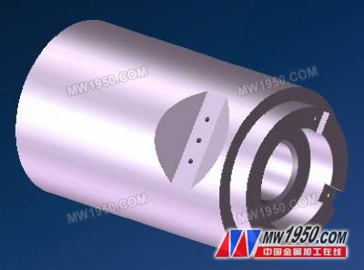
This workpiece is a product of a military enterprise. It needs to be processed in the ordinary 2-axis turning part. It needs to be clear that there is a U-shaped groove on the cylindrical surface that needs to be milled. In addition, it needs to drill 3 holes. Of course, it needs to be used. Go to the C axis to mill the two U-grooves and drill holes in the end face.
â— GibbsCAM has excellent physical reading capability. After directly reading the corresponding model, most of the processing can be completed by creating blanks, basic 2-axis vehicles, drilling, and boring. When it is necessary to machine U-shaped grooves and holes on the end face, it is necessary to use the C-axis function. When machining U-shaped grooves and holes on the cylindrical surface, the function of the Y-axis is used. First create a new coordinate system (CS) on the corresponding feature.
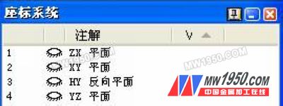
â— The coordinate system (CS) is indispensable in the Y and C axis machining of GibbsCAM. The calculation of the relevant points of the CNC machine tool is also obtained by CS.
â—Because in GibbsCAM programming, when you define the turning and milling compound machining operation, 4 sets of coordinate planes are automatically generated in the coordinate system (CS). Of course, you can continue to create more coordinate systems as needed.
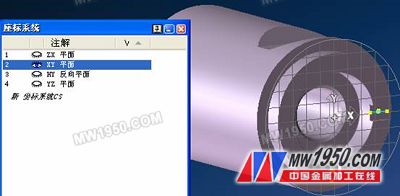
â— As mentioned above, the 2-axis turning, drilling and boring have been basically completed. The latter is mainly the milling function of the C-axis and the Y-axis. Let us look at the processing of the two U-shaped grooves and the two holes of the end face, because At the end face, so we need to use the C axis machining operation. We also said that the coordinate system is very important when writing the Y and C axis programs, but it has been helped when you define the turning and milling operation. We define the coordinate system XY plane of the end face C axis.
â— Below we will perform some surface processing according to the set coordinate system, first switch to the XY plane:
| Previous page | 1 | 2 | 3 | 4 | Next page |
1. Description
Naipu G series Gravel and sand slurry pump is
designed specifically for continuous pumping of extremely aggressive
slurries, with a wide particle size distribution. Capable of handling
large particles at consistently high efficiencies results in low cost of
ownership. The large volume internal profile of the casing reduces
associated velocities further increasing component life.
Typical Applications---
Slag Granulation
Suction Hopper Dredging
Dredging
Barge Loading
Sand Reclamation
Sugar Beet
2. G series gravel and sand slurry pump construction drawing

3. G series gravel and sand slurry pump select chart

4. G series gravel and sand slurry pump performance parameters

River Sand Pump,Horizontal Gravel Pump,Sand Dredging Pump,Gravel Sand Slurry Pumps
Shijiazhuang Naipu Pump Co., Ltd. , https://www.naipu-pump.com