In the field of CNC machining, the automatic programming method of CATIAV5R20 can easily realize the NC programming of parts and generate high-efficiency and high-precision NC program. On the other hand, it can test whether there is obvious overcut or interference by physically simulating the tool path. Phenomenon, timely modification, thus greatly improving the actual processing efficiency, thereby shortening the production cycle and bringing greater benefits to the enterprise.
1. CATIA automatic programming steps
(1) Use CATIA 3D modeling to build part solid graphics in mechanical design or shape design module, or directly import existing solid models.
(2) In the processing module, the blank part is created according to the external dimensions of the part and the machining allowance.
(3) The machining environment and operation definition of the parts, including the machine setting, the determination of the machining coordinate system, the definition of the target parts and blanks, and the determination of the safety plane.
(4) According to the forming requirements of the parts, select reasonable processing methods, such as roughing step, sweeping step, residual material clearing angle, contour processing, shape cutting, axial machining, etc.
(5) Select the tool, cutting parameter, forward and backward tool path, etc. corresponding to the machining method.
(6) Tool path simulation, observe the cutting situation, and determine whether there is cutting interference.
(7) Post-processing and output of the NC machining program.
2. Case analysis
This paper takes the CATIA automatic programming method of the ornamentation process elephant as an example for analysis. The small image processing material is nylon, which is formed by a rough and fine milling secondary processing method.
(1) Open the CATIA [Mechanical Design] module, select [Part Design], select the "XY Reference" surface,
Enter [Sketch], select the [Spline] function, draw a sketch according to the shape of the process image, as shown in Figure 1, and stretch forming, the thickness is 12mm (see Figure 2).
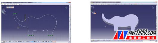 Figure 1 Figure 2
 (2) Enter the [Processing] section, select [SurfaceMachining], enter the surface processing module, select [RoughStock] in the [GeometryManagement] menu, create raw material, and the system will pop up the "RoughStock" definition blank dialog box. According to the size of the small image, we Set to X100mm, Y53mm, Z12mm.
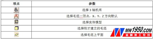
Select [PartOperation.1] under [Process] in the feature tree to set the machining, complete the selection of the machine tool, determine the origin of the coordinate system, select the part and blank, and determine the safety plane (see Table 1 for specific parameters).
Table 1
(2) Select [ManufacturingProgram] under [Process] in the feature tree, click [Insert] → [MachiningOperations] → [RoughingOperations] → [Roughing] to enter the contour milling program, and the system pops up “Roughing. 1" dialog box.
First define the tool path

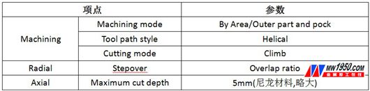
The specific parameters are shown in Table 2. Observe the software schematic and select the parameters.

The pop-up diagram (see Figure 3) shows the setting effect of each parameter according to the schematic diagram. And when selecting the [Toolpathstyle] tool path mode and the [Cuttingmode] cutting mode, it is necessary to judge whether to use the spiral or the back and forth according to the actual machining condition, whether it is down-cut or up-cut.
Table 2
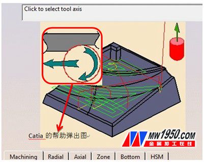 image 3
 Secondly define the processing area

, select the blank and the part, the software will automatically calculate the processing area, the setting method is shown in Figure 4. This step is the most important step in the program setting. The correct choice of the processing area directly affects the success of the program establishment.
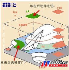 Figure 4
 Enter tool selection

, the software will recommend some tools according to the part processing program, choose

And set some parts of the tool, cancel [Ball-endtool] check, select [More>>], set the tool radius, length, fillet, etc. according to the actual machine tool and tool configuration. Here we set [Nominaldiameter] to 8mm ( See Figure 5).
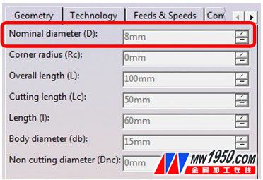 Figure 5
 Set tool chip parameters

, define the machining feed rate. Set [Machining] in [Feedrate] to 200mm/min, and [Machining] in [ApindleSpeed] to 800turn/min. Note that you must uncheck [AutomaticcomputefromtoolingFeedsandSpeeds], otherwise F and S cannot be defined (see Figure 6). .
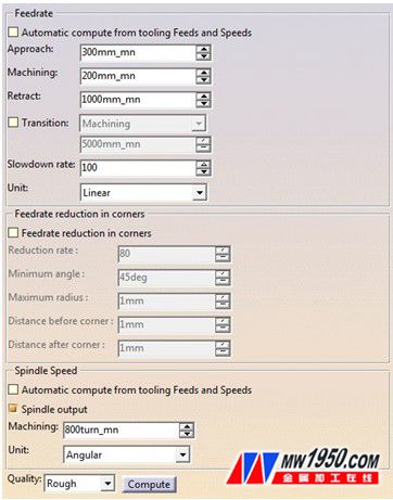 Image 6
 The final step in the contour drop roughing program setting is the in/out path setting.

Since it is a rough milling program, select [Ramping] in [Automatic], and the rest will use the default settings.
(3) Here you can simulate the rough milling program, click [ToolPathReplay]

,bomb
Out of the dialog box shown in Figure 7, select

Click later

The simulation process of forming the blank can be observed (see Figure 8). Pay attention to whether the tool path is consistent with the assumption and ensure that there is no interference.
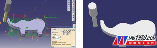 Figure 7 Figure 8
 For the same reason, click [Insert] → [MachiningOperations] → [ProfileContouring], select the shape milling program to finish the shape of the small image of the process, no longer repeat here, select reasonable parameters according to the processing requirements, and simulate the processing effect. It is important to pay attention to the milling contour. When selecting the side, it must be closed side line; [Approach] and [Retract] must select [Circularhorizontalaxial] to reduce damage to the finished surface, as shown in Figure 9 and Figure 10.
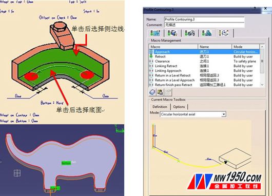 Figure 9 Figure 10
 (4) After completing the above operation, it is also necessary to convert the numerical control tool path into a numerical control program (NCProgram) which can be recognized by the numerical control machine through GenerateNCCode. CATIAV5 offers two methods, one is Batchmode (batch mode) and the other is Interactivelymode (interactive processing mode), here we choose the former. Click in [NCOutputManagement]

Select [In/Out] → [NCdatatype] → [NCCode], [NCCode] → [IMSPost-processorfile] → [siemens840] (can be selected according to the operating system of the CNC device), as shown in Figure 11, click [Execute] The software will automatically generate an NC program to complete the automatic programming process of the process image.
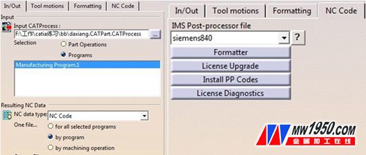 Figure 11
 3. Precautions
Through the above case, we noticed that the automatic programming with the CATIAV5 processing module should pay attention to the following points:
(1) Use the CATIA programming process to flexibly use the “hidden†and “display†functions of each component in the feature tree. Especially when defining the machining area, it is necessary to select the blank and the part separately. This function can achieve twice the result with half the effort.
(2) Flexible application when some parameters of CATIA are not well understood

Features.
(3) When the process is complicated, the machining program must be inserted in the appropriate position of the feature tree in the order of the process, so that the programmed program is coherent.
(4) When the program is output, the IMA postprocessor must be set: [Tools] → [Options] → [Processing] → [Output] → [PostProcessorandControllerEmulatorFolder] → [IMS], otherwise the NC system cannot be used.
Kubota Hydraulic Parts
Kubota excavators and compact track loaders have gained a worldwide reputation for quality and reliability in skid steer and excavator machinery.
Accordingly, JUHENG are pleased to match these qualities of Kubota's with a wide range of genuine, OEM and quality replacement parts for Kubota compact track loaders and mini excavators. These include Final Drive, swing drive, hydraulic pump and slew ring for all Kubota skid steer and excavator models.
Parts for Kubota Skid Steer and Excavator Machines
Investigate below the stock availability for your Kubota excavator part. If a unit is available and you order before 3pm we despatch worldwide the same day.
To find out more about our range and our repair and reconditioning services, click on the part type you require under 'Brand Parts We Stock'
If you require a Kubota hydraulic pump, click our Kubota Main Pump finder to investigate options and request a quote.
Hydraulic Piston Pump, Duplex Pump, Short-Stroke Pump, Noise/Vibration Reduction, High Self-Priming Ability, Rotational Stability, High Efficiency, High Pressure, Compact Size, Reduction of Overall Length.
Kubota hydraulic pumps provide low-noise, high efficiency and high reliability with various controls for construction machinery.
We export GENUINE PUMP, OEM PUMP, AFTERMARKET PUMP. We are specialized in OEM PUMP & AFTERMARKET PUMP. We export 95 NATIONS. Please contact us If you need STABLE SUPPLIER.
Kubota Hydraulic Main Pump,Kubota Main Hydraulic Pump,Kubota Hydraulic Pump,Kubota Hydraulic Pump Spare Parts,Kubota Hydraulic Main Pump Assembly,Kubota Main Pump,Kubota Pump,Kubota Hydraulic Parts,Kubota Excavator Parts
Jining Juheng Hydraulic Machinery Co., Ltd. , https://www.sdjuhengmachine.com