1. Reversible welding and cutting positioner technical content and implementation plan
(1) Technical content How to use a new type of equipment to realize the automatic cutting of the transition groove of the mill cylinder flange, the mixing barrel section and the ring gear frame and the automatic welding of the weld seam, which can save time and effort and improve efficiency To ensure quality and safety, and to achieve continuous and efficient production is the core technology of this research. In order to effectively solve various problems in the welding process, to ensure the welding quality and production cycle, after repeated research and structural design, the reversible welding and cutting position machine was developed.
This equipment is a slow speed device with a motor selected by strict calculation. After changing the transmission direction and transmission ratio through the size of the bevel gear, the power is transmitted to the pinion gear, and then the pinion drive is used to drive the gear of the large gear. The cylinder to be welded is fixed on the equipment, and the operation is performed at a speed satisfying the welding, so that the operator or the welding machine is not moved in place, and the welded workpiece is welded at a constant speed to ensure the quality and quantity are completed. At the same time, the device also uses the electric motor to transmit power to the worm in the lifting device through the linkage device, the worm transmits the power to the turbine, and the rotation of the turbine drives the connecting rod to lift and lower, thereby completing the turning action. Through the above actions, the cutting and welding of the groove can be completed.
(2) Embodiment The welding and cutting rotary table is composed of a large gear transmission device, a supporting device, a slow speed device, a turning device, a pinion gear device, a jacking device, a welding base, a top seat and an electric motor. Figure 1 is a schematic view of the structure of a welding and turning turntable.
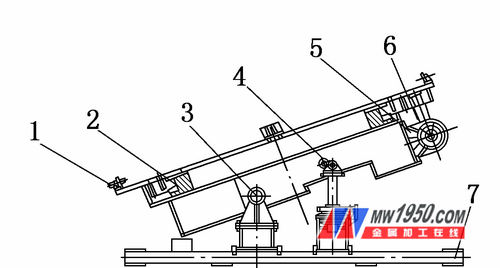
figure 1
1. Tightening device 2. Large gear transmission 3. Support device 4. Inverting device 5. Slow speed device
6. Pinion gearing 7. Welding base
The working principle is as follows: First, the large gear device is composed of a chuck, a pressure plate, a hollow shaft, a copper tile, a bearing and a large gear. The chuck is designed in the form of a weld, which is assembled by combining the bolts and pins with the large gears. The lower end of the large gear is designed with a stop and a bearing upper cover of the one-way thrust bearing to cooperate to complete the common rotation. The inner hole of the large gear is designed to be combined with the copper tile to complete the support during the tilting process; the hollow shaft is designed in the form of a stepped shaft, and the uppermost axial step is combined with the pressure plate to press the large gear to prevent the turning When the big gear is disengaged. The lowermost axial step in the middle is matched with the bearing lower cover of the one-way thrust bearing. Thus, when the large gear starts to rotate, the chuck and the bearing upper cover rotate with each other, thereby completing the relative rotation of the chuck and the hollow shaft. Figure 2 is a schematic illustration of the structure of a large gear unit.
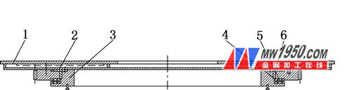
figure 2
1. chuck 2. pressure plate 3. hollow shaft 4. bearing upper cover 5. copper tile 6. large gear
Secondly, the turning device is used to adjust the tilting angle of the device. It is composed of a connecting rod device, a lifting device, a turbine bearing, a linkage device, a limiting device and a worm device. The connecting rod device is composed of a connecting rod, a connecting rod pin shaft and the like; the lifting device is composed of a turbine, a nut, etc.; the worm device is composed of a worm and a support. The working principle is that the motor is connected to the worm on both ends of the device through the linkage device, the worm drives the turbine to rotate, the inner hole of the turbine is matched with a nut, and the connecting rod is lifted and lowered by the rotation of the nut. The worm gear mechanism has a self-locking function for safer use. Since the trajectory of the flip is an arc and the trajectory of the link is a straight line, a link is designed to ensure the flip trajectory. Figure 3 is a schematic illustration of the turning device.

image 3
1. Turbine 2. Nut 3. Linkage device 4. Lifting device 5. Worm device 6. Linkage device
Finally, the pinion gear (see Figure 4) is mainly composed of a pinion, a small bevel gear, a large bevel gear and the like. The motor drives the large bevel gear to rotate by the slow speed device. The large bevel gear changes the direction of rotation to 90° through the small bevel gear. The small bevel gear transmits the power to the pinion gear, and finally the pinion gear transmits to the large gear. In order to reduce the height of the equipment, the design chooses to turn the motor laterally. In order to complete the transmission, a pair of bevel gears are designed to complete the direction change.
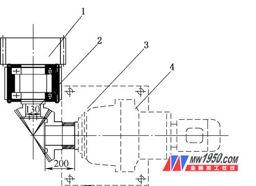
Figure 4
1. Pinion 2. Small bevel gear 3. Large bevel gear 4. Slow motor
2. Application effect of reversible welding and cutting positioner
(1) The use of the reversible welding and cutting positioner makes the precision of the original mill cylinder flange, mixing barrel section and ring gear frame can only be completed by large vertical car. Now it can be completed by water welding cutting. , reducing costs.
(2) The use of the reversible welding and cutting positioner enables the original operator to rotate around the workpiece, adjust the angle welding, and change the workpiece to rotate and flip, ensuring the welding quality.
(3) The design of the reversible welding and cutting positioner is compact and the principle is clear. The automation of cutting and welding increases the efficiency and is convenient to use.
(4) The reversible welding and cutting positioner technology is suitable for the bevel welding of large cylinder and flange products; the workpiece rotation replaces the operator to rotate the welding, which improves the welding efficiency; eliminates the large vertical turning of the vertical cutting Reduced production costs.
Gate Valves,Gate Valve ,Slide Gate Valve,Sluice Gate Valve
WENZHOU DIYE VALVE&FITTINGS CO.,LTD , https://www.diye-valve.com