1 Introduction
This paper introduces the project is the key new product development project of Tianshui Great Wall Switch Factory from 2002 to 2003. It is a new medium-voltage switchgear “XGNE-40.5†developed for the Qinghai-Tibet Railway. "XGNE-40.5" is a 40.5kV voltage class. It uses SF6 gas as the insulating medium and uses C-GIS switchgear with vacuum breaking. It is a new high-tech power distribution device developed internationally. Compared with other switching devices of the same voltage class, "XGNE-40.5" has the advantages of small size, high reliability and maintenance-free, so it can adapt to various harsh operating environments.
Tianshui Great Wall Switch Factory is a professional manufacturer of power transmission and transformation switchgear with the highest annual output in China with 33 years of history. It mainly produces 0.4~35kV high voltage switchgear, 3~35kV high voltage electrical components and low voltage switch. cabinet. The products are widely used in national large and medium-sized power engineering and industrial projects, and exported to more than 20 countries and regions.
Electricity is an important source of energy for supporting the construction and development of the national economy and the basis for the sustainable development of China's national economy. At present, China's power supply is generally tight, and power consumption has maintained rapid growth. The market prospects for the power transmission and transformation equipment manufacturing industry, especially the medium voltage switch manufacturing industry, are very broad.
Due to the increasingly fierce market competition and the impact of well-known foreign companies, in order to speed up the product development speed of our new switchgear, it is imperative to introduce new concepts and methods in the design and manufacture of switchgear. After the successful application of 2D CAD technology in product design, our factory purchased the PTC company's mechanical design automation software system Pro/ENGINEER, Pro/Motion and Pro/Structure to improve the product design efficiency and promote the standardization of design tools. Design software for auxiliary design work. A series of new product development projects including "XGNE-40.5" were carried out using the PTC solution.
2 Project objectives using PTC solutions
(1) Due to market demand and the urgent requirements of the company's new product development plan, the product must complete the entire process from research and development to production within two years.
(2) The 3D simulation model of the product can be seen in the early stage of the product. At the same time, any profile of interest in the product model can be easily observed in the 3D environment as the basis for engineering selection.
(3) The top-down assembly design is used. In the design, the outer wheel part of the component can be used to consider the reserved space, and then replaced with the detailed design component in the subsequent design. Part design can also be done in the assembly to ensure the shape and accuracy of the assembly. It is also possible to check the assembly situation by performing a function related to the gap check.
(4) Through the analysis of the mechanism and the generated motion simulation, we can see the speed, position and acceleration of the components we care about, and initially verify the correctness of the work of the mechanism.
(5) Research and optimization of the motion mechanics of the motion part of the product design.
(6) Research and optimize the structure of product design.
(7) Behavior modeling generates the shape of key parts of key components.
(8) Generate a dynamic demonstration of the assembly process and interlocking process of the switchgear, provide training for the assembler and maintenance personnel of the switchgear, and provide clear demonstration and teaching for users and visitors.
(9) The full relevance of database content and the reusability of engineering data in the product design process.
3 Project content using PTC solution
3.1 CAD solid geometry modeling (using Pro/ENGINEER to build mathematical models)
The geometric model is used to build the mathematical model of the product inside the computer. In geometric modeling, we strive to do the following.
(1) Defining the design intent, creating a geometric model, and deriving the geometric model from the design requirements. Using features and design benchmarks to generate a 3D solid, you can view its shape in 3D space; when you need to modify a part, you only need to modify the size or add features.
(2) Full correlation and parameterization based on feature modeling. Full correlation means that any change in the design process is reflected in the process from design to processing to ensure consistency and coordination across all parts and processes. Parameterization refers to the use of well-known features as the structural elements of the geometric model of the product. It is easy to design multiple times by setting parameters for these features and then modifying the parameters to achieve product development.
(3) Assembly relationship management in product design. The components are placed in suitable positions to determine the assembly relationship between the system components. The system automatically arranges the assembly relationship of the components according to the given constraints. For example, if the assembly-related dimensions of a part are changed, it is related to zero. The component position or constraints are automatically changed.
3.2 CAE function simulation (using Pro/Mechanica for optimization analysis)
(1) Interference inspection and structural inspection. By calculating the space volume of each component, it is possible to find out the parts of the product structure design that interfere with each other early and ensure the correctness of the product design.
(2) Perform mechanism motion simulation. Understand the organization's operation, study the sensitivity of the organization, automatically optimize the mechanism to meet specific goals and constraints, and be able to calculate the relationship between the motion in the assembly and the forces that affect the motion. Using these calculations, you can optimize the design by changing the parameters to achieve the best design. Specifically, the following tasks can be accomplished: verifying the spatial relationship of the mechanism model simply and quickly; synthesizing the cam profile using behavior modeling functions and studying the parameter changes under the corresponding motion conditions; specifying the actual load in the motion of the motion driver simulation mechanism Optimize the mechanism model to study changes in parameters and stress conditions in various possible situations during exercise.
(3) Structural optimization design. Evaluate the performance of the product under certain load conditions, predict the performance of the product in the actual use environment, study which design parameters have the greatest impact on the structural characteristics, and optimize the geometry. Model any type of structure in the product design concept, compare the advantages and disadvantages of each program through CAE analysis results; apply different load constraints, observe the changes of various parameters and related structural design variables; perform structural shape optimization and sensitivity analysis, Find the best working point; for the design, output the results in multiple formats to facilitate the sharing of design data.
4 PTC solution implementation process and results
The application of PTC solution in this work mainly goes through three stages according to the design process (as shown in Figure 1), and adopts two PTC software modules: Pro/ENGINEER 2001 and Pro/Mechanica.
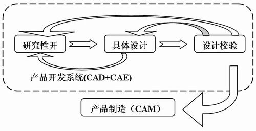
Figure 1 Product development process using PTC solution for this project
4.1 Research development stage
In the research development stage, the main task is to determine the concept and purpose of the overall design in the future, that is, based on the designer's creative concept, combined with the functional design of the design object to develop the overall design. Solve problems such as “what kind of structure and drive method to useâ€, “what is the estimated parameter value to be achieved†and “what kind of material to use†that affect the specific design stage. The main work content is to apply Pro/ENGINEER and related modules to conceptualize the initial form of the drive mechanism, establish 3D models of several original ideas, create corresponding layout frameworks, compare and determine the design schemes in an intuitive form, and determine the relevant Engineering problems that need to be solved, and at the same time determine the division of labor and authority allocation during the design process.
0.07ml/rev Gear Pump,Electro-magnetic drive pump,Ceramic printing pump,Electromagnetic metering Pump
Suzhou Macxi Fluid Technology Co.,Ltd. , https://www.macxipump.com