Through the introduction of the project of Jingbo Agrochemical Technology Co., Ltd., this paper focuses on the functions and significance of the Acrel-6000 electrical fire monitoring system.
Yang Junjun
Ankerui Electric Co., Ltd. Shanghai Jiading
1 Introduction
Jingbo Agrochemical Technology Co., Ltd. is located in Boxing County, Binzhou City, Shandong Province. It is involved in pesticide research and development, raw drug synthesis, preparation processing, plant nutrition product development and production, packaging printing, crop quality and high yield management program, planting. A modern high-tech enterprise that integrates modern comprehensive services and mechanized plant protection services.
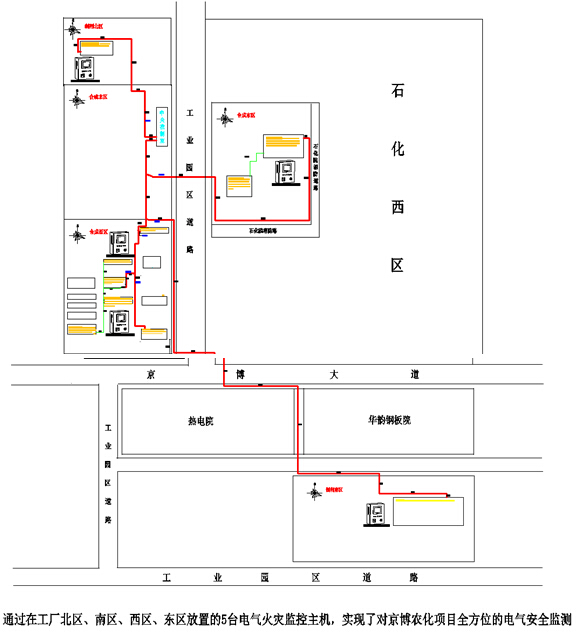
The project consists of three sub-projects: Jingbo Culture Project (100,000 tons of ether ester), Jingbo Agrochemical Technology Co., Ltd. project, Jingbo Agrochemical Technology Co., Ltd. Xincheng Printing Industry Branch project, including preparation North District There are 5 power distribution rooms in the power distribution room, the synthesis one power distribution room, the synthetic three power distribution room, the synthetic six power distribution room, and the preparation south area power distribution room.
Overall, the project can be divided into two parts: the western area and the eastern part. The western area includes the synthesis and distribution room (south), the synthesis and distribution room (north), the 3# transformer room, the synthesis three distribution room, and resources. Comprehensive utilization of the power distribution room, the eastern area includes the synthesis of five distribution rooms, the synthesis of six distribution rooms. There is a residual current monitoring point in each power distribution cabinet.
2. System requirements analysis
This project is a factory project, and the area is large. If a distribution line leaks, the relevant personnel cannot find it in time. The Acrel6000 electrical fire monitoring system should be able to accurately monitor the faults and abnormal conditions of electrical circuits, identify fire hazards of electrical fires, and promptly alert the relevant personnel to eliminate these hidden dangers and prevent electrical fires.
3. Reference standard
This system complies with the National Standard of the People's Republic of China GB14287.1-2005 "Electrical Fire Monitoring System Part 1: Electrical Fire Monitoring Equipment".
4. System structure
The Acrel-6000 electrical fire monitoring system is an industrial grade that is independently developed by the company to receive field devices such as residual current electrical fire detectors to achieve alarm, monitoring, control, and management of protected electrical circuits. Hardware/software system. The system is applied to the fire control center of large shopping malls, living quarters, production bases, office buildings, shopping malls and other areas, and telemetry, remote adjustment, remote control and remote signaling of detectors scattered in the building are convenient for monitoring and management. The system uses a standard Modbus field bus to connect detectors with communication functions. When the detected parameter in the field protection circuit exceeds the alarm set value, it can send out alarm signals and control signals, can indicate the alarm part and save the alarm. information.
At the project site of Jingbo Agrochemical Technology Co., Ltd., there are 55 ARCM300-J8 electrical fire detectors and 17 ARCM300-J4 electrical fire detectors distributed in various power distribution rooms. The on-site electrical fire detector uses the bus method to access the Acrel-6000 wall-mounted electrical fire monitoring system via the 485 bus. The system has the advantages of convenient installation and transportation, high cost performance and convenient maintenance.
The main equipment of the Acrel-6000 electrical fire monitoring system is as follows:
Main control unit: industrial grade tablet with touch screen, WinCE operating system
1 Input and output: Built-in intelligent DCMOD module developed by the company with multiple input and output
2 sound and light alarm: built-in speaker, LED indicator
3 Backup power supply: 2 sections 12V/7.2Ah maintenance-free battery
Host panel component layout and function description
1: Alarm indicator (red): When the device receives the alarm signal from the detector, the alarm indicator is always on.
2: Fault indicator (yellow): When the system fails (such as communication failure, power failure, etc.), the fault indicator is always on.
3: Running indicator (green): When the device is running normally, the indicator light is always on.
4: Main power indicator (green): When the main power is normal, the monitoring device is powered by the main power supply. At this time, the main power indicator is always on.
5: Standby power indicator (green): When the main power supply is under voltage or fault, the monitoring equipment is powered by the backup power supply, and the standby power indicator is always on.
The system is distributed using a distributed network structure, as shown in the following figure:
1) Station management
The management of the station control management system for the electrical fire monitoring system is the direct window of human-computer interaction and the uppermost part of the system. Mainly composed of system software and necessary hardware equipment, such as industrial-grade tablet computers, micro-printers, UPS power supplies. The monitoring system software has a good human-computer interaction interface, calculates, analyzes, and processes various types of data information on the site, and responds to the on-site transportation situation by means of graphics, digital display, sound, and indicator lights.
Monitoring host: used for data collection, processing, and data forwarding. Provides data interfaces for system management, maintenance, and analysis within and outside the system.
Printer: System call prints or automatically prints graphics, reports, alarm logs, and more.
UPS: Ensure the normal power supply of the computer monitoring system, and ensure the normal operation of the station management management equipment when the whole system has power supply problems.
The main unit of the electrical fire monitoring system is installed in the fire control room.
2) Network communication layer
Communication medium: The system mainly uses shielded twisted pair cable to connect to the fire control room monitoring host by RS485 bus to realize real-time communication between field device and host computer. The communication line is laid along the weak bridge to ensure the quality of the communication.
3) Field device layer
The field device layer is a data acquisition terminal, mainly for the ARCM300 electrical fire detector and the AKH-0.66L series leakage current transformer (as shown in the figure below). ARCM300 can monitor 4 or 8 channels of leakage current, each channel has disconnection and short circuit detection function; with event storage function, the alarm can record the time, type and parameter of alarm occurrence, and can analyze the power consumption situation according to the alarm record. To provide a basis for eliminating faults; using fieldbus communication technology, the host computer management software can monitor the operation of the scene at all times and timely discover the alarm information. The standard MODBUS protocol can be connected to a variety of standard systems; high integration, networked, and highly intelligent.
5. System function
This set of PC software Acrel-6000 electrical fire system. Mainly has the following features: friendly human-machine interface, real-time and time-consuming collection of residual current data of field devices, and alarm prompt sound and light alarm and other functions. The customer can set the leakage current alarm value according to actual needs. When the alarm fault is released, it can be reset remotely. The system can record alarm events, dates, alarm values, and crossing values, and generate reports to print alarm event records.
1) Monitoring main interface
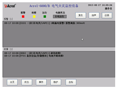
The data collected by the on-site ARCM300L electrical fire detector is uploaded to this interface. The customer can modify the circuit name as needed. The real-time value of the residual current of the corresponding cabinet can be displayed in the square, and the data can be updated periodically. When the measured value of residual current is greater than the alarm setting, the system alarm status indicator will flash automatically. The alarm prompt scroll bar at the lower end of the interface will automatically prompt the alarm circuit name to facilitate the operation personnel to check and handle the fault.
2) Detector communication failure information prompt interface
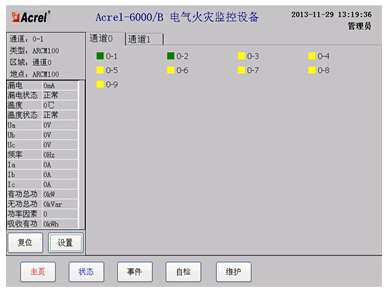
This interface mainly realizes the remote adjustment function. The operation personnel can query the residual current over-the-counter alarm value of the corresponding loop in the parameter setting report, and set the residual current over-the-counter alarm value according to the actual needs of the site. At the same time, the alarm instrument can be remotely reset. When the fault alarm is released, press the reset button to perform remote reset, which is convenient for users.
3) Event record query interface
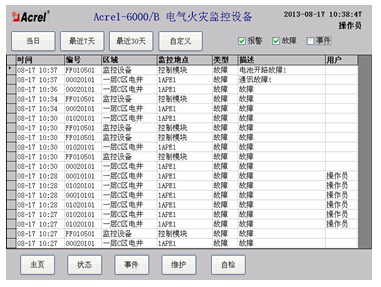
With event storage function, the alarm can record the time, type, parameter and alarm value of the alarm. According to the alarm record, the fault can be analyzed to provide a basis for eliminating the fault; and the alarm record can be printed.
6. Conclusion
With the development of intelligent buildings and the widespread use of electricity, people's awareness of safety is becoming higher and higher. Installation of leakage fire system in public buildings is an inevitable trend of intelligent construction. The electrical fire system is conducive to the detection of potential safety hazards, timely handling of safety hazards, and the importance of fire prevention and precaution. Since the system was put into operation, many hidden dangers have been discovered and rectified, which provided a scientific basis for the fire management of the project and was well received by customers.
references
[1]. Ren Zhicheng Zhou Zhong. Principles and Application Guidelines of Power Electrical Measurement Digital Instrumentation [M]. Beijing. China Electric Power Press. 2007. 4
[2]. Zhou Zhong. Application of power meter in electric energy metering of large public buildings [J]. Modern Building Electric 2010. 6
About the author: Yang Junjun, female, undergraduate. Position: Now working for Ankerui Electric Co., Ltd., contact number, mobile phone, QQ
Http://news.chinawj.com.cn Editor: (Hardware Business Network Information Center) http://news.chinawj.com.cn
4 Inch Floor Trap,4 Inches Floor Drain,Stainless Steel 4 Inch Floor Trap,4 Inches Square Shower Drain
Kaiping City Jinqiang Hardware Products Co.,Ltd , https://www.jmkimpowerdrain.com