The terminal block shown in Figure 1 is a part of an electrical product. It is made of 1 mm thick cold-rolled steel plate. The production batch is large. It was originally processed in a single process. The process steps are: cutting strips, punching holes, Punching and cutting the bending part, cutting, rounding and bending, a total of five processes, a long cycle, and the need to use four sets of special molds, not only affect the production efficiency of the enterprise and is not conducive to the positioning of parts, dimensional accuracy is not easy to guarantee, In the last compounding process of rounding holes and bending, the former process has been cut into small pieces with a shape of only 20 mm × 12 mm, which causes inconvenience to operation and positioning. In order to meet the production requirements of the enterprise and improve the operating conditions, a multi-station progressive die was designed to meet the above requirements while ensuring the quality of the parts.
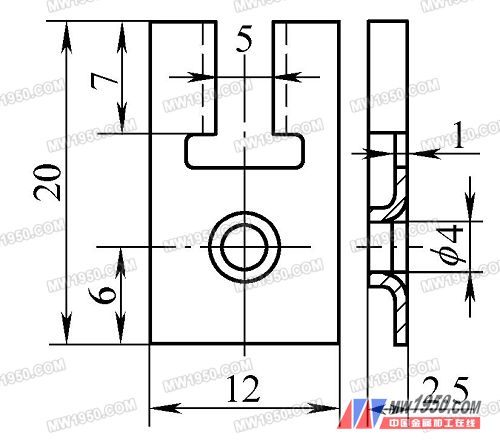
Figure 1 Block structure diagram
Process analysis
The structure of the part is not complicated. It is a forming and bending assembly, and the height of the round hole flanging is not large. After calculation, the height of the flanging after the pre-punching can be formed at one time.
It is noted that the dimensions of the parts are small, the dimensional accuracy of the parts is not high, the production volume is large, and at the same time, considering the processing and manufacturing capabilities of the parts, it is decided to design the multi-station progressive die.
2. Layout design
In order to improve production efficiency and material utilization rate, the entire layout is carried out in a symmetrical arrangement of two parts to design a two-piece mold structure.
The machining of the parts is divided into 5 stations, namely: punching circular holes → punching the middle rectangular holes → prefabricated holes for punching and bending parts → rounding holes and bending → cutting into parts, and the production of two workpieces is completed every press. According to the above analysis, the determined part layout scheme is shown in Figure 2.
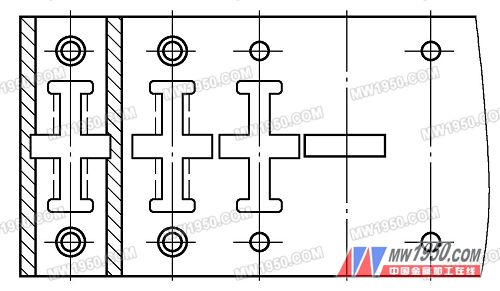
Figure 2 parts layout diagram
3. Mold design
(1) mold structure and working process
According to the part layout drawing, the mold structure shown in Fig. 3 is designed.
Next page
A Dove prism is a type of reflective prism which is used to invert an image. Dove prisms are shaped from a truncated right-angle prism. A beam of light entering one of the sloped faces of the prism undergoes total internal reflection from the inside of the longest (bottom) face and emerges from the opposite sloped face.dove prisms are ideal for image rotation.Dove Prisms have two application. One is creating an image inversion in beam input parallel to the base. Another application is used as a retroreflector. it perform as a right-angle prism. have an unusual and very interesting characteristic - if you look through the prism and rotate it around a longitudinal axis
Images passing through the prism are flipped, and because only one reflection takes place, the image's handedness is changed to the opposite sense. Dove prisms have an interesting property - when they are rotated along their longitudinal axis, the transmitted image rotates at twice the rate of the prism. It is very important that the application must be used with parallel or collimated beam and the large square reflective surface should be kept very clean. Another application is used as a retroreflector.


Optical Glass Dove Prism,Silicon Dove Prism,Uncoated Dove Prism
Changchun Ruiqi Optoelectronics Co.,Ltd , https://www.ruiqi-optics.com