Abstract: This paper introduces the function selection, tool setting and data display circuit design principle of economical numerical control system. The introduced method can enhance the system function, is convenient to operate, and reliable in operation.
The hardware and software design of the economical CNC system directly affects the machining performance and operational performance of the CNC system. This paper introduces some problems and treatment methods often encountered in the hardware design of economical numerical control system.
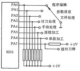
There are several different ways to select the system function. When using the CRT display as the display terminal, you can create a function menu, and the user can select the function through the menu. However, in order to reduce the cost, the economical numerical control system generally does not use a CRT display, but uses a digital tube to form a display terminal. At this time, the band switch can be used to form a function selection circuit through the parallel interface. 1 is a schematic diagram of a function selection circuit composed of an interface circuit 8255 and a band switch. Program editing - entry, inspection and modification of the machining program. Parameter setting - set the drive gap, G00 speed, tool parameters, etc. File processing - machining program loading and unloading, etc. Tool setting - Manual and automatic detection of tool position and radius parameters and automatic storage into the system. Manual processing - manual feed. Continuous processing - continuous execution of the machining program. Single-segment processing - one processing step at a time.
In the main program after the system is started and in the subsequent functional programs, the position of the band switch is detected through the 8255 cycle and transferred to the corresponding function module.
The tool setting method adopted in the economical CNC system of our lathe can realize manual tool setting and automatic tool setting. The insulating round bar of a certain size is made of metal material, insulated from the machine tool, and the tool is grounded through the machine tool. When the tool is turned, the tool holder drives the tool closer to the tool bar, and the tool signal is sent to the system through the PA75 of the 8255. The system receives a high level when the tool tip is not in contact with the tool bar, and the system receives a low level when the tool tip is in contact with the tool bar.
There are three options after entering the tool setting function: manual tool setting, automatic tool setting and calculation of tool compensation values.
Manual tool setting mode, display the current tool position number, manually change the tool with the tool change button of the keyboard, and move the tool with the arrow keys (horizontal or vertical) of the keyboard. When the tool is in contact with the tool bar, the tool movement automatically stops and saves its moving distance, and continues to wait for the keyboard operation. When you choose to exit the manual tool setting, the manual tool setting function is exited and the tool setting master program is returned.
In the automatic tool setting mode, first ensure that the tool starts from the 1st position and displays the current tool position number. The automatic tool setting is divided into a longitudinal tool setting and a horizontal tool setting. In the vertical automatic tool setting, the tool moves from the first tool to the tool bar and records the moving distance of the tool. The tool is retracted to the original position and automatically changed to the second tool. Contact the tool bar and record the moving distance of the tool until all the tools complete the tool setting and automatically save the tool moving distance. The method of horizontal automatic tool setting is the same as the longitudinal direction, except that the tool moves in a different direction. When you choose to exit the automatic tool setting function, the automatic tool setting function is exited and the tool setting master program is returned.
The tool compensation calculation is to calculate the position difference between the other tools after the tool is placed relative to the first tool and store the calculation result in the tool compensation parameter area of ​​the system.
The displays of economical CNC systems are mostly composed of digital tubes. The digital tube display can be either a dynamic display or a static display.
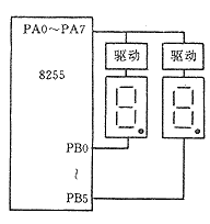
The dynamic display uses fewer components and the circuit is simple. The principle is shown in Figure 2. A row of digital tubes has a segment display and a bit display address. Only one digital tube is shown in the figure. The segment display is used to control the character to be displayed (glyph code), and the bit display is used to control which digital tube is displayed. To make a digital tube display a certain character, first send the font code to be displayed to the segment display address, and then make the bit corresponding to the digital tube in the bit display data 1 (or 0), and the other bits are 0 (or 1), then send the data to the address.
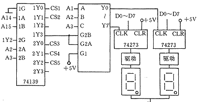
The static display uses many components and the circuit is complicated. Each digital tube has a segment display address and no bit display address. Each digital tube has a latch that latches the data to be displayed. This display method does not disappear as long as it does not send new data to the digital tube. If the display data is unchanged, there is no need to display the refresh. Only when the data to be displayed changes, it is necessary to inject the data to be displayed to the display. Because the system has EPROM (used to store the system program), RAM (used to store the processing program), interface circuit 8255 (used as input, output), etc., each piece of memory must have a certain address range, and the digital tube address Can be continuous. To solve this problem, two-level decoding can be used. The circuit principle is shown in Figure 3. In the figure, CS1 is used as the EPROM chip select signal of the system, CS2 is used as the RAM chip select signal of the system, and CS3, CS4 and CS5 are used as the 8255 chip select signals of the system. The 3-8 decoder is used to process the display. If there are multiple rows of digital tubes in the system, multiple 3-8 decoders can be used. Different 3-8 decoders A, B, and C are connected to different address lines. .
The hardware and software design of the economical CNC system directly affects the machining performance and operational performance of the CNC system. This paper introduces some problems and treatment methods often encountered in the hardware design of economical numerical control system.
 Figure 1 function selection and tool processing circuit principle |
1 function selection
There are several different ways to select the system function. When using the CRT display as the display terminal, you can create a function menu, and the user can select the function through the menu. However, in order to reduce the cost, the economical numerical control system generally does not use a CRT display, but uses a digital tube to form a display terminal. At this time, the band switch can be used to form a function selection circuit through the parallel interface. 1 is a schematic diagram of a function selection circuit composed of an interface circuit 8255 and a band switch.
In the main program after the system is started and in the subsequent functional programs, the position of the band switch is detected through the 8255 cycle and transferred to the corresponding function module.
2 tool setting
The tool setting method adopted in the economical CNC system of our lathe can realize manual tool setting and automatic tool setting. The insulating round bar of a certain size is made of metal material, insulated from the machine tool, and the tool is grounded through the machine tool. When the tool is turned, the tool holder drives the tool closer to the tool bar, and the tool signal is sent to the system through the PA75 of the 8255. The system receives a high level when the tool tip is not in contact with the tool bar, and the system receives a low level when the tool tip is in contact with the tool bar.
There are three options after entering the tool setting function: manual tool setting, automatic tool setting and calculation of tool compensation values.
Manual tool setting mode, display the current tool position number, manually change the tool with the tool change button of the keyboard, and move the tool with the arrow keys (horizontal or vertical) of the keyboard. When the tool is in contact with the tool bar, the tool movement automatically stops and saves its moving distance, and continues to wait for the keyboard operation. When you choose to exit the manual tool setting, the manual tool setting function is exited and the tool setting master program is returned.
In the automatic tool setting mode, first ensure that the tool starts from the 1st position and displays the current tool position number. The automatic tool setting is divided into a longitudinal tool setting and a horizontal tool setting. In the vertical automatic tool setting, the tool moves from the first tool to the tool bar and records the moving distance of the tool. The tool is retracted to the original position and automatically changed to the second tool. Contact the tool bar and record the moving distance of the tool until all the tools complete the tool setting and automatically save the tool moving distance. The method of horizontal automatic tool setting is the same as the longitudinal direction, except that the tool moves in a different direction. When you choose to exit the automatic tool setting function, the automatic tool setting function is exited and the tool setting master program is returned.
The tool compensation calculation is to calculate the position difference between the other tools after the tool is placed relative to the first tool and store the calculation result in the tool compensation parameter area of ​​the system.
3 display processing
The displays of economical CNC systems are mostly composed of digital tubes. The digital tube display can be either a dynamic display or a static display.
The dynamic display uses fewer components and the circuit is simple. The principle is shown in Figure 2. A row of digital tubes has a segment display and a bit display address. Only one digital tube is shown in the figure. The segment display is used to control the character to be displayed (glyph code), and the bit display is used to control which digital tube is displayed. To make a digital tube display a certain character, first send the font code to be displayed to the segment display address, and then make the bit corresponding to the digital tube in the bit display data 1 (or 0), and the other bits are 0 (or 1), then send the data to the address.
 Figure 2 shows the schematic diagram dynamically |  Figure 3 static display circuit schematic |
The static display uses many components and the circuit is complicated. Each digital tube has a segment display address and no bit display address. Each digital tube has a latch that latches the data to be displayed. This display method does not disappear as long as it does not send new data to the digital tube. If the display data is unchanged, there is no need to display the refresh. Only when the data to be displayed changes, it is necessary to inject the data to be displayed to the display. Because the system has EPROM (used to store the system program), RAM (used to store the processing program), interface circuit 8255 (used as input, output), etc., each piece of memory must have a certain address range, and the digital tube address Can be continuous. To solve this problem, two-level decoding can be used. The circuit principle is shown in Figure 3. In the figure, CS1 is used as the EPROM chip select signal of the system, CS2 is used as the RAM chip select signal of the system, and CS3, CS4 and CS5 are used as the 8255 chip select signals of the system. The 3-8 decoder is used to process the display. If there are multiple rows of digital tubes in the system, multiple 3-8 decoders can be used. Different 3-8 decoders A, B, and C are connected to different address lines. .
Led Lighting,Led Strip Lights,Led Lights For Room,Led Bulb
Zhongshan Tiger Lighting Co.,Ltd. , https://www.tigerstreetlight.com